1. What is an Ultrasonic Distance Sensor ?

Ultrasonic Sensor
is a popular and low cost solution for non-contact distance measurement
function. It is able to measure distances from 2cm to 400cm with an
accuracy of about 5mm. This module includes ultrasonic transmitter,
ultrasonic receiver and its control circuit. it can be used with all most micro-controller .
HC-SR04/5 module has 4 pins :


3. How to use it with Arduino or Stm32 :
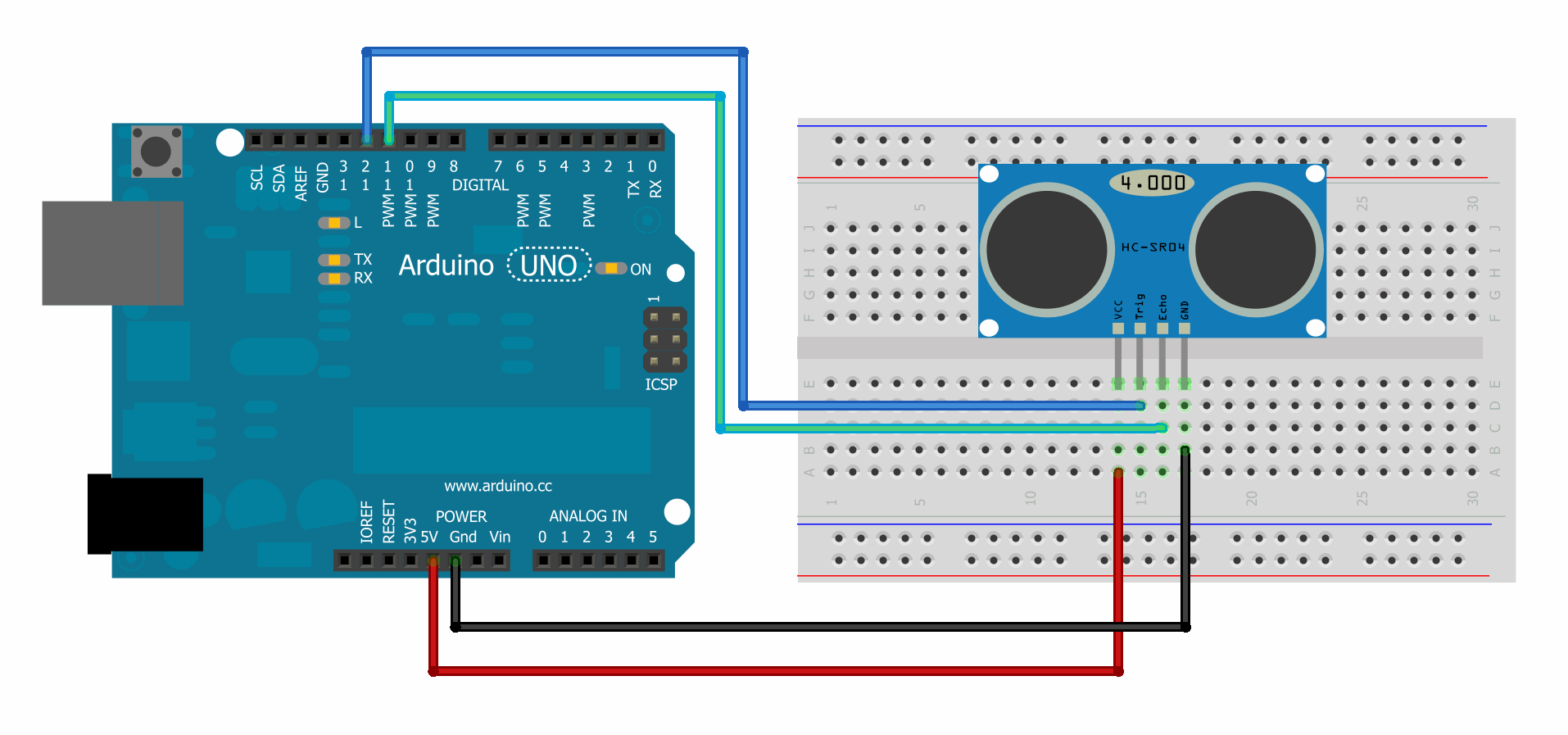
- Wire connection and code for Arduino
- VCC pin to the Arduino 5v
- GND pin to the Arduino GND
- TRG pin to the Arduino Digital pin 12
- ECHO pin to the Arduino Digital pin 11
HC-SR04/5 module has 4 pins :
- VCC – 5V of the power supply
- TRIG – Trigger Pin
- ECHO – Echo Pin
- GND – to ground
2. How Does an Ultrasonic Sensor Work?
- Ultrasonic sensor principle
Ultrasonic sensors emit short, high-frequency sound pulses at regular intervals. These propagate in the air at the velocity of sound. If they strike an object, then they are reflected back as echo signals to the sensor, which itself computes the distance to the target based on the time-span between emitting the signal and receiving the echo.
- Interfacing with microcontroller
- Provide TRIGGER signal, at least 10μS High Level (5V) pulse.
- The module will automatically transmit eight 40KHz ultrasonic burst.
- If there is an obstacle in-front of the module, it will reflect the ultrasonic burst.
- If the signal is back, ECHO output of the sensor will be in HIGH
state (5V) for a duration of time taken for sending and receiving
ultrasonic burst. Pulse width ranges from about 150μS to 25mS and if no
obstacle is detected, the echo pulse width will be about 38ms.

- How to Find the Range of Target ?
The image bellow explain how to calculate the range.
The image bellow explain how to calculate the range.
- Wire connection and code for Arduino
- VCC pin to the Arduino 5v
- GND pin to the Arduino GND
- TRG pin to the Arduino Digital pin 12
- ECHO pin to the Arduino Digital pin 11
the code example : (source : arduinobasics.blogspot.com)
/*
 HC-SR04 Ping distance sensor:
 VCC to arduino 5v
 GND to arduino GND
 Echo to Arduino pin 11
 Trig to Arduino pin 12
 */


#define echoPin 11 // Echo Pin
#define trigPin 12 // Trigger Pin
#define LEDPin 13 // Onboard LED

int maximumRange = 200; // Maximum range needed
int minimumRange = 0; // Minimum range needed
long duration, distance; // Duration used to calculate distance

void setup() {
 Serial.begin (9600);
 pinMode(trigPin, OUTPUT);
 pinMode(echoPin, INPUT);
 pinMode(LEDPin, OUTPUT); // Use LED indicator (if required)
}

void loop() {
/* The following trigPin/echoPin cycle is used to determine the
 distance of the nearest object by bouncing soundwaves off of it. */
 digitalWrite(trigPin, LOW);
 delayMicroseconds(2);

 digitalWrite(trigPin, HIGH);
 delayMicroseconds(10);

 digitalWrite(trigPin, LOW);
 duration = pulseIn(echoPin, HIGH);

 //Calculate the distance (in cm) based on the speed of sound.
 distance = duration/58.2;

 if (distance >= maximumRange || distance <= minimumRange){
 /* Send a negative number to computer and Turn LED ON
 to indicate "out of range" */
 Serial.println("-1");
 digitalWrite(LEDPin, HIGH);
 }
 else {
 /* Send the distance to the computer using Serial protocol, and
 turn LED OFF to indicate successful reading. */
 Serial.println(distance);
 digitalWrite(LEDPin, LOW);
 }

 //Delay 50ms before next reading.
 delay(50);
}
- VCC pin to the stm32f4 5v
- GND pin to the stm32f4 GND
- TRG pin to PD10
- ECHO pin to PD11
You can get all project from my git account HERE
#include "stm32f4_discovery.h"
#include "delay.h"

uint32_t Read_Distance(void);
void Init();

uint32_t distance ;

int main()
{
    Init();   // initialisation de pin
    SysTick_Init(); // pour pouvoire utiliser la fonction delay :)

    while (1)
    {
    distance=Read_Distance();
    delay_nms(100);
    }
}


void Init()
{
    RCC_AHB1PeriphClockCmd(RCC_AHB1Periph_GPIOD, ENABLE);

    GPIO_InitTypeDef gpioStructure;

    gpioStructure.GPIO_Pin = GPIO_Pin_10;
    gpioStructure.GPIO_Mode = GPIO_Mode_OUT;
    gpioStructure.GPIO_Speed = GPIO_Speed_100MHz;
    GPIO_Init(GPIOD, &gpioStructure);

    gpioStructure.GPIO_Pin = GPIO_Pin_11;
    gpioStructure.GPIO_Mode = GPIO_Mode_IN;
    GPIO_Init(GPIOD, &gpioStructure);
}
//Les Pins pour le Test sont PD10 (Trig) et PD11(echo)

uint32_t Read_Distance(void)
{
          __IO uint8_t flag=0;
           __IO uint32_t disTime=0;
    GPIO_SetBits(GPIOD,GPIO_Pin_10);
    delay_nus(10);
    GPIO_ResetBits(GPIOD,GPIO_Pin_10);

  while(flag == 0)
  {
   while(GPIO_ReadInputDataBit(GPIOD,GPIO_Pin_11) == SET)
   {
     disTime++;
     flag = 1;
   }

  }
    return disTime;
}


0 commentaires:
Enregistrer un commentaire