This article represent a routing solution for a WPAN or WSN based on random walk algorithm . the used transceiver is spirit1 you can find its firmware with our implemented solution on my github account
The Internet of Things (IoT), defined by the Oxford dictionary as a proposed development of
the Internet in which everyday objects have network connectivity, allowing them to send and
receive data, is the next big thing in embedded computing. Most of the information available
on the Internet is made and added by human beings, but the IoT can change all this data
collection by connected widgets.
A boom owing to the arrival of the IoT is expected to connect a very large number of devices
to the Internet. One major drawback was the limitation of 4.3 billion unique addresses posed
by the IPv4 protocol. This issue was addressed with the development and subsequent adaptation
of IPv6, which allows a nearly unlimited number, 2128, or approximately 3.4×1038 unique
addresses. Gartner, the American research firm, predicts nearly 26 billion devices on the IoTby 2020.
It is a well known fact that wireless connectivity is a key component of the Internet of Things
(IoT). Embedded systems in various disciplines, such as transportation, medical, smart grid, industrial, home and automation, are more often than not integrated with wireless connectivity
called machine-to-machine (M2M) communication. These systems need not necessarily be
M2M-capable, but these do include an assortment of sensors and other devices.
The main problem of M2M solutions is the higher cost of devices that allows your system to
connect to the internet. So we are interesting to minimize the cost of developing of theses
technologies.
In fact , one of the most used device for communication is the GSM modem due
to it large coverage. But using this type of communication always has a cost additional for
users who should pay the subscription fee. So it is very important to find a less costly solution
for the deployment of M2M platform that respect the requirement.
Machine to Machine technology (M2M)
The development of communication technologies and intelligent devices combined with
enterprise computing, enabled the emergence of a new type of uses and applications: the
Machine To Machine or M2M.
M2M
The Machine To Machine is the association of information and communications technology
with intelligent and communicating objects in order to interact together without human
intervention.
The use of the machine-to-machine is particularly suitable for interacting with a large number
of devices that can be fix or mobile.
The M2M technologies facilitates the management of high number of devices. It also allows
companies and organizations to develop new services in their works.
M2M Architecture
M2M allows a bidirectional exchange between the M2M device and
the application. The received information will be processed. In many cases, M2M involves a
group of identical devices interacting with an application.
In some cases, the devices can‘t communicate directly with the application because of their
limited capacity. In this case, a device called ‘Gateway’ is necessary to ensure the
communication.
Global Architecture
Deployment architecture
The overall architecture is used to give an overview on the various nodes of our network,
from this vision, we will detail the main role of each node.
Three things form basic building blocks of our M2M system. End nodes or Meter , routing
Node (router) and concentrator .
Each of these nodes has to have certain characteristics in order to form an effective system as
explained further.

Meter :
It is the front-most node of any IoT system. In some cases, these objects could also perform
dual role as sensors or input devices as well as actuators or output devices.
Their main job is to collect or disseminate data (or do both). Meters need to have unique
identifier in order to identify them and communicate with them effectively in large array of
end-nodes in bigger M2M application.
Meters can be controlled with command-control mechanism and this may be either autonomous
or may be handled by the end-users directly.
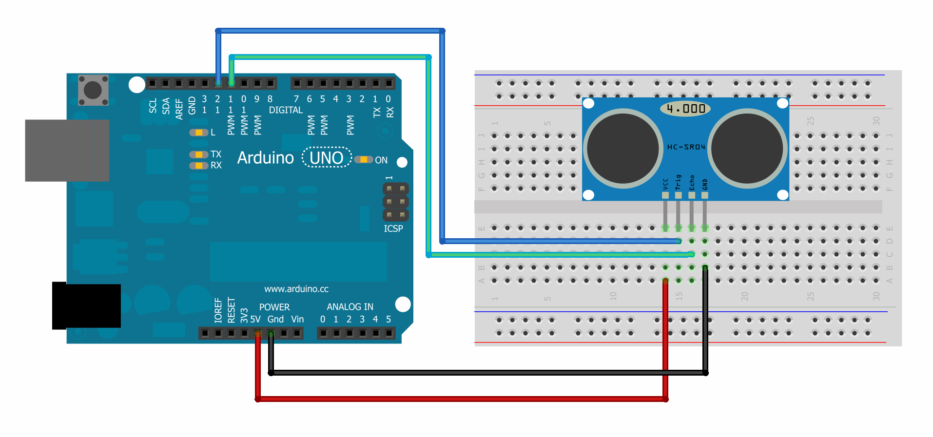
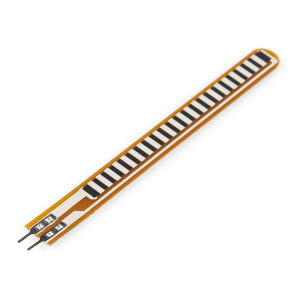
Typical examples of end nodes could be humidity sensor, temperature sensor, MEMs, radar
vision, ultrasonic sensors, RFID readers, flow meters, cameras, GPS etc.
Router :
A router is a specialized networking device allows to move data from meters that are outside
the coverage to the concentrator. It is always activated so it needs to be powered by a power
supply.
In our application , the router can do the same job of meter and send its own information to the
concentrator (or receive commands ).
the router configuration is dynamic and can be changed by the concentrator in order to improve
the performance of our system and get the optimal path.
Concentrator
: This section does form central part of our system and can be considered as a heart of IoT
or M2M solution. The main job of this node is to process the data and information received
from meters or routers and transmit to further link for action which may be software application
or cloud based service. It also sends the information received from application to the meters or
router (configuration).
Concentrators nodes provide local intelligence to the entire network of sensors and application.
While heavy lifting software is based on cloud network or individual PCs, processing nodes
form small computing elements in local infrastructure.
These can be easily controlled with command-control mechanism by application software and
mostly work on real-time basis. Its also performs encryption and decryption of data to maintain
security of communication.
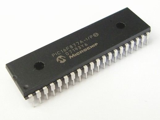
Typically a Concentrator involves one or more microcontrollers, microprocessors, hybrid
circuits, etc. and may be relatively bigger in size as compared to meters.
Topology
Nodes operating modes allows a partial mesh topology. A mesh network is a network topology
in which each node relays data for the network. All mesh nodes cooperate in the distribution of
data in the network. Mesh networks can relay messages using a routing technique. With routing,
the message is propagated along a path by hopping from node to node until it reaches its
destination.
Detailed design
Internal Architecture:
As we explained in the global architecture , our application is composed from three device
(Meter , Router , Concentrator). Each device has a necessary element to do its tasks.
for example the Meter need some sensors (or actuator) to collect or disseminate data while the
concentrator need other device (example : GSM Modem or Wifi ) to establish an internet
connection. However all device need a common element which is the transceiver to
communicate together.
All these additional elements will be integrated to a microcontroller. To guarantee that the
system will operate autonomously and support multitasking , a state machine will be
implemented to allows the parallel execution of tasks and organize the program by layer.
While all device will use a common transceiver , the program will contain a common layer
which are : Network , Mac_driver that will be explained later with detail.
In addition to these two layer , each Node has its own application layer to do its tasks.
the Routing node can listen to all devices to route any packet come from meter/concentrator
that are outside the coverage ofthe concentrator/meter. However , both Meter and Concentrator
will accept only a packet that is destinated for them (a low level filter will be enabled).

Design of different layer
=> Mac driver layer
The aim of this layer is to manipulate the main operation which are send or receive data. it begin
with initializing the communication between the microcontroller and the transceiver and
configure some parameter (modulation , band frequency , type of packet ... ). Then this layer
will wait for request to send or listen for incoming data and manage Csma-ca engine.
- IDLE : This state will wait for request from the superior layer
- RX : Turn off csma-ca engine and listen for incoming data. if any data is received it will
be saved on temporary buffer and the state will change to Received_data_ready
- Received_data_ready : the state will be detected by the superior layer and it means that
there is new data saved in Rx buffer.
- TX : Turn on csma-ca engine and send data saved on Tx buffer to the destination address
- Wait_Tx_Flag : In this state , the machine will wait until the channel will be empty and
the transmission is done.
=> Network layer
This machine have two waiting
line , one for the messages to send called Txfifo and the other for the received data called Rxfifo.
Both are using First-In, First-Out algorithm.
- Message state in TxFIFO :
- Empty : in this state the packet is empty and the superior layer can put its message that want
to send
- Ready_to_send : in this state the packet is ready to send and waiting for it turn.
- Sending : this state means that the message is sending right now and waiting for acquittal
- Message state in RxFIFO :
- Empty : In this state if any data is received this packet is empty and ready to save it.
- Rx_msg : this state is to inform that it contain new message ready to be readed.
=> Meter application layer
The flowchart belows models the Meter application layer. this device have
to build a packet of informations periodically or eventually depending on application. Once the
message is ready the machine will send it to TxFIFO of Network layer and wait for acquittal in
case of need.
- BUILD_MSG : In this state the machine will wait for any interruption or period deadline
to build a new packet with updated informations.
- SEND_DATA : The machine will send the ready message to the Network layer and
exactly to the TxFIFO. Then if the packet need to be acquitted the machine will wait
for acquittal. Else it will return to the initial state which is BUILD_MSG.
- WAIT_ACK : This state is to wait for the concentrator to send it acquittal

=> Concentrator application layer
As we mentioned in the global architecture the role of concentrator is to process the data and
information received from meters or routers and transmit to the server. in case the packet need
to be acquitted the machine will support this task.
- LISTENING : in this state the machine will listen for incoming packet from the
RxFIFO (Network layer)
- SEND_DATA_TO_SERVER : In this state (after receiving new packet) the new data
will be send to the server using Tcp/Ip connexion.
- SEND_ACK : Send an acquittal for each packet in case of need.
=>Router application layer
- Principal of random walk : A random walk is a mathematical formalization of a path that consists of a succession of
random steps. For example, the path traced by a molecule as it travels in a liquid or a gas, the
search path of a foraging animal, the price of a fluctuating stock and the financial status of a
gambler can all be modeled as random walks, although they may not be truly random in
reality. The term random walk was first introduced by Karl Pearson in 1905. Random walks
have been used in many fields: ecology, economics, psychology, computer science, physics,
chemistry, and biology. Random walks explain the observed behaviors of many processes in
these fields, and thus serve as a fundamental model for the recorded stochastic activity

Our routing algorithm is based on random walk , all routers have a threshold (probability of
transmission) that is used to make a decision. In addition to the threshold the packet will have
a field called ‘prefered address’ that is used also for decision. when a packet is received , the
router will analyse it to make one of the following decision :
1- if the packet is destined for the broadcast address (0xFF) , then the router will get a
random number in [0..100] (Get_Random) using its Timer and compare it to the
threshold. if the random number is upper than the threshold , the packet will be
forgotten. Else the router will send it to the destination after a period (WAIT) calculated
using the random number (random number * 2 ms).
2- if the field ‘prefered address’ is equal to the router address , then the packet will be
routed to the destination directly (Send_Msg)
3- if the field ‘prefered address’ is not equal to the router address Or the packet routed
many time ( fixed at fifth time ) , then the message will be forgotten.

Frame format
- Application layer :
Data is used to save the information that will be send to the server. this field can be
programmed by the developer which is an actor for our application
- Network layer :
Source : the address of the original device who send the packet that can be a meter or
concentrator
Destination : the address of destination device that can be meter or concentrator
Preferred address : used to define a specific route and if it is equal to the broadcast address
the router will forward it using its intelligent algorithm (random walk)
Sequence number of the message.
Type of the message that define if the meter need an acquittal or not. And also for the
concentrator to define if it is a command or an acquittal (ACK).
Routers to count the number of router and describe the route of packet in of tests
- Mac driver layer :
Preamble (programmable field): the length of the preamble is programmable from 1 to 32
bytes. Each preamble byte is a '10101010' binary sequence.
Sync (programmable field): the length of the synchronization field is programmable (from 1
to 4 bytes). The SYNC word is programmable through registers SYNC1, SYNC2, SYNC3, and
SYNC4. If the programmed sync length is 1, then only SYNC word is transmitted; if the
programmed sync length is 2 then only SYNC1 and SYNC2 words are transmitted and so on.
Length (programmable/optional field): the packet length field is an optional field that is
defined as the cumulative length of Address, Control, and Payload fields. It is possible to
support fixed and variable packet length. In fixed mode, the field length is not used.
Destination address (programmable/optional field): when the destination address filtering
is enabled in the receiver, the packet handler engine compares the destination address field
of the packet received with the value of register TX_SOURCE_ADDR.
Payload (programmable/optional field): the device supports both fixed and variable payload
length transmission from 0 to 65535 bytes.
CRC (programmable/optional field): There are different polynomials CRC: 8 bits, 16 bits (2
polynomials are available) and 24 bits. When the CRC automatic filtering is enabled, the
received packet is discarded automatically when the CRC check fails.

Hardware environment
Host device: STM32L151 Discovery
The choice of STM32L151 DISCOVERY as host device is based on many
reasons. This device extend the ultra-low-power concept with no compromise on performance,
using the Cortex-M3 core and a flexible CPU clock from 32 kHz up to 32 MHz. As well as the
dynamic run and low-power run modes, two additional ultra-low-power modes bring you very
low power consumption while keeping an RTC, backup register content and low-voltage
detector.
The STM32L151/152 devices are designed for medical, industrial and consumer applications
and feature an onboard fast 12-bit 1 MSPS ADC, USB 2.0 FS and capacitive touch sensing.
To reduce application cost and design, the STM32L151/152 offer an integrated LCD driver
with up to 8 x 40 segments.
SPIRIT1 Low data rate, low power Sub 1GHz transceiver
The SPIRIT1 is a very low-power RF transceiver, intended for RF wireless applications in the
sub-1 GHz band. It uses a very small number of discrete external components and integrates a
configurable baseband modem, which supports data management, modulation, and
demodulation. The data management handles the data in the proprietary fully programmable
packet format also allows the M-Bus standard compliance format (all performance classes).
However, the SPIRIT1 can perform cyclic redundancy checks on the data as well as FEC
encoding/decoding on the packets. The SPIRIT1 provides an optional automatic
acknowledgement, retransmission, and timeout protocol engine in order to reduce overall
system costs by handling all the high-speed link layer operations.
Moreover, the SPIRIT1 supports an embedded CSMA/CA engine. An AES 128-bit encryption
co-processor is available for secure data transfer. The SPIRIT1 fully supports antenna diversity
with an integrated antenna switching control algorithm. Transmitted/received data bytes are
buffered in two different three-level FIFOs (TX FIFO and RX FIFO), accessible via the SPI
interface for host processing.

The SP1ML-868 and SP1ML-915
To simplify our development and test task , we used The SP1ML-868 and SP1ML-915. They
are ultra-low power & fully integrated RF modules operating respectively in the 868 MHz SRD
and 915 MHz ISM bands.
The SP1ML module is a compact-size module, integrating an on-board antenna with easy-to
use interface, allowing users to easily add wireless connectivity in designs and reducing time
to-market.
These modules are based on the SPIRIT1 RF sub-GHz transceiver (with integrated SMPS),
STM32L1 microcontroller, integrated filter/balun and chip antenna. The UART host interface
allows simple connection to an external microcontroller with a standard firmware, allowing
AT commands to facilitate RF configuration, data transmission and reception, using simple
point-topoint communication. Selected STM32L1 GPIO and peripherals are available for
interfacing to external devices in the user application.
Advanced features of the SPIRIT1 radio are also accessible. The serial wire debug interface
(SWD) is also available. The modules are CE compliant and FCC certified (FCC ID
S9NSP1ML)

Different tests
Main program
The figure belows shows our main program with the different type of device. The infinite loop is organized and contain the routine of all layers. The developer can easily select the type of
device and modify on it.
Test of Csma-CA engine
CSMA mode is used in order to avoid collisions when attempting to access the communication
channel.The figure belows shows the different devices used to evaluate the Csma-CA engine.
These devices are Meter (A) which is used to send a packet and a concentrator (B) to receive
it. A sniffer (D) is used for testing the transmission. A noise generator device (C) is used to
generate a continuous wave in order to occupy the channel to permit the validation of the
CSMA feature enabled on the Meter device of this example.
The result shown in figure belows was perfect and the Meter (A) send its packet only after
we turned off the noise generator device (C).
Test of Meter , router and concentrator
- Test of two meters with concentrator In this test we used two meters and one concentrator. these meters are sending their packets
periodically. The figure shows the result of this test. At the first the meter that have 0x20
as address send a packet (1) that need an acquittal. then the concentrator will send for it a packet
(2) that it type is acquittal. the same scenario will be repeated (3+4) for meter with address
equal to 0x30
- Test of meter router and concentrator
In this case we introduced a router device with one meters and one concentrator. The figure shows the result of this test. At the first the meter send a packet (1) that need an acquittal
and has 0xFF (broadcast address) as preferred route. So the router will forward (2) it using its
intelligent algorithm (Random walk) and add it address in routers field. Then the concentrator
will receive the message and send (3) it acquittal (ACK). Finally the router will forward the
packet again (4) , but this time to the meter.
References :
[1] ST Micoelectronis Spirit1 Low data rate, low power sub-1GHz transceiver (11-02-2015)
[2] Data sheet SPIRIT1 RF, DM00047607 (18-2-2013)
[3] Data sheet SP1ML, DM00133214 (27-2-2015)
[B5] St WIRELESS M-BUS IN SMART GRID SCENARIO
[B6] Data sheet STM32L151x6/8/B (30-Jan-2015)
[4]http ://emcu.it/WirelessMBUS/Wireless_M-BUS_Solutions_and_more (27/07/2015)
[5] http://electronicsofthings.com (01-08-2015)
This
project is realized by Nidhal Mars, an engineering student at ENSI, “Embedded
Software and Systems” specialization through a summer internship (2015) .
This article is extracted from my report. For any needs feel free to contact me .


